What Are the Key Benefits of Smart Film for Car Sunroofs
Learn more >


Automotive smart film design involves more than matching a film to the outline of a piece of glass. The arrangement of transparent and switchable areas, the position of electrical connections, and the boundaries between functional zones all influence how the finished glazing looks and operates. Pattern etching provides a way to define these areas within the film structure while accommodating the requirements of a particular vehicle application.
For automotive manufacturers and smart film suppliers, the main challenge is to ensure that the intended pattern can be manufactured accurately and integrated into the glazing assembly without compromising switching performance. A pattern that looks suitable in a design drawing may still create problems if its boundaries conflict with the glass layout or if its electrical isolation requirements are not considered early enough.
A well-developed automotive smart film pattern therefore requires coordination between product design, film processing, electrical configuration, and glass assembly. Each decision should be assessed against the vehicle's actual requirements rather than treated as an isolated decorative feature.
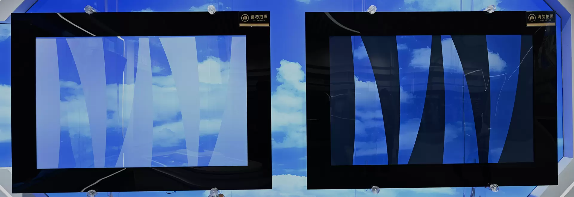
Smart film used in automotive glazing is generally based on a functional liquid crystal layer combined with transparent conductive layers and supporting film materials. When an appropriate electrical field is applied, the liquid crystal structure changes its optical state. The resulting appearance depends on the film construction and the specific product design.
Pattern etching is a processing method used to remove selected portions of a conductive layer or create defined electrical separation lines. In suitable designs, this separation allows different areas of the film to be arranged according to a planned electrical configuration. The exact result depends on the film structure and the manufacturer's processing method.
This distinction matters because pattern etching does not automatically create every possible optical effect. A visual pattern, a separately controlled dimming zone, and an area that remains permanently transparent are different design requirements. They may need different film structures, conductive layouts, or additional processing steps.
Before developing an etched pattern, the engineering team should establish what the pattern is expected to achieve.
l Electrical separation: Defined isolation lines can separate conductive regions where the design requires independent electrical paths.
l Functional zoning: Selected areas can be configured for different switching requirements when the film construction and control system support that arrangement.
l Defined non-switching areas: Certain regions may need to remain outside the active switching area, depending on the intended construction.
l Integration with vehicle components: Pattern boundaries can be planned around mounting features, trim, electrical connections, or other areas that affect the final glazing assembly.
These functions should not be assumed to be interchangeable. For example, isolating two conductive regions does not by itself guarantee independent control. Each intended switching zone must also have a suitable electrode arrangement, electrical connection, and control strategy.
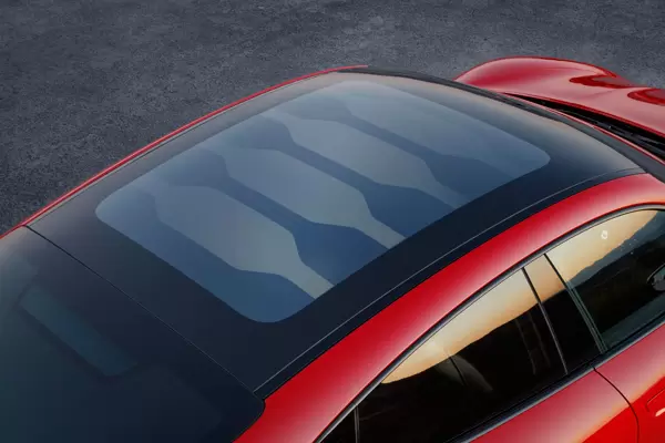
Automotive glass rarely offers a simple rectangular working area. Windshields, sunroofs, rear windows, and side glazing have different contours and installation requirements. Even when two glass panels have similar overall dimensions, their functional areas and connection locations may differ considerably.
Pattern etching must therefore be developed around the actual glazing geometry rather than an approximate outline.
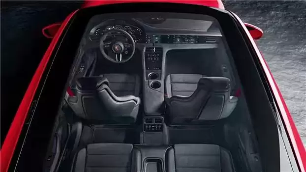
A sunroof may contain a broad central area with curved corners and limited space around the perimeter. The visible film area may also differ from the full glass dimensions because of the surrounding frame, masking, or mounting structure.
For this type of application, the etched pattern needs to remain within the approved film layout. Isolation lines should not unintentionally divide the intended switching area, while connection regions must remain accessible for the planned electrical assembly.
Panoramic roofs can introduce additional considerations because of their larger surface area and more complex outlines. If the design includes multiple functional zones, their boundaries should be evaluated against the complete roof layout and the intended control arrangement.
Side windows often have tapered profiles, angled edges, or curved sections that restrict the available film area. Door structures and trim can also affect where electrical connections can be positioned.
Rear windows may present a different set of constraints. Their curvature, edge profile, and existing glazing features can influence the available space for the film and its connections. Where other electrical functions are present in the glass assembly, their locations should be reviewed during pattern development.
In both applications, the objective is to preserve the required active area while maintaining sufficient clearance for installation and electrical routing. A pattern should not be approved solely because it fits within the nominal glass outline.
One of the most important engineering considerations in pattern etching is the relationship between the etched layout and the film's electrical configuration.
A smart film system requires a suitable electrical field across its active area. If the conductive structure is divided into separate regions, each region must be designed with the appropriate electrical connections and isolation requirements. Poorly defined boundaries can make assembly more difficult and may affect the intended switching behavior.
The engineering review should address several points.
Isolation line placement
The position of each isolation line should correspond to the intended electrical separation. Lines that are too close to connection areas or other conductive features may create processing and assembly difficulties. The required isolation width should be determined from the film construction and the supplier's manufacturing capabilities rather than selected arbitrarily.
Electrode and busbar arrangement
Conductive regions need an appropriate connection layout. The busbar or electrode arrangement should be coordinated with the etched pattern so that the intended area receives the required electrical supply. Connection positions must also suit the available space within the glass assembly.
Independent zone control
If the application requires separate switching zones, the electrical design must support that requirement from the beginning. Each zone may require its own connection path and compatible control arrangement. A pattern drawing alone is not sufficient evidence that independent operation will be achieved.
Boundary consistency
The etched layout should be checked for unintended intersections, incomplete isolation, and inconsistencies between adjacent functional regions. These checks are particularly important when a design contains several boundaries or irregularly shaped zones.
Electrical separation should be verified through appropriate inspection and testing. Visual examination can identify obvious pattern defects, but it cannot replace electrical checks when isolation and zone control are part of the product specification.
Pattern etching can support more deliberate control over the appearance of automotive smart film. However, the visual result depends on the entire glazing assembly, not just the shape of the etched lines.
The position of a boundary may appear acceptable on a digital drawing but become more noticeable when viewed through finished glass. Lighting conditions, surrounding trim, glass curvature, and the position of the film within the assembly can all influence the perceived result.
Designers should evaluate the pattern in the context of the actual vehicle interior and exterior.
A few practical considerations deserve attention:
l Visibility of boundaries: Etched separation lines should be positioned with their potential visibility in mind. Whether a line remains noticeable depends on the conductive structure, the film construction, and the surrounding optical layers.
l Consistency between zones: Adjacent switching areas should be reviewed for differences in appearance when they change optical state. The required visual consistency should be defined before sample approval.
l Relationship with black borders and trim: Areas hidden by an opaque border or covered by a mounting component may provide useful space for connections or other design features, provided the construction permits it.
l Appearance in the finished assembly: Pattern evaluation should use representative glass and installation conditions whenever possible. A loose film sample may not accurately reflect the final appearance.
There is also a practical limit to how much detail a pattern should contain. Additional lines and smaller functional regions increase the number of design features that must be processed, inspected, and coordinated with the electrical layout. A complex pattern may be justified for a specific vehicle requirement, but unnecessary detail can increase manufacturing difficulty without providing a meaningful functional benefit.
The best design is not necessarily the most complicated one. It is the design that achieves the required appearance and switching behavior while remaining compatible with the production process.
The quality of an etched pattern depends on more than the accuracy of its original drawing. The specified layout must be translated into a repeatable processing result, and the finished film must remain suitable for subsequent assembly.
Pattern verification should begin with the approved engineering data. The drawing needs to identify the active regions, isolation boundaries, connection areas, and relevant dimensional references. Ambiguous lines or inconsistent reference points can lead to different interpretations during processing and inspection.
During sample evaluation, the following characteristics should be checked against the agreed requirements.
Acceptance criteria should reflect the actual film design and manufacturing process. For example, a dimensional tolerance suitable for one pattern may not be appropriate for another with narrow isolation lines or closely spaced connection regions.
Inspection methods also need to match the characteristics being evaluated. Dimensional inspection can confirm pattern placement, while suitable electrical tests are needed to verify isolation and switching behavior. Optical inspection provides a separate check of the visible result.
These checks should be defined before sample production. Waiting until a finished glazing assembly reveals a problem can make it harder to determine whether the cause lies in the pattern drawing, film processing, electrical connection, or installation method.
Pattern development becomes more efficient when the film supplier receives complete and consistent engineering information. Missing details can lead to repeated drawing revisions, sample delays, and disagreements over which areas are included in the approved design.
The initial design package should normally address the following information, where applicable:
l The approved glass drawing and film orientation.
l The required active switching area and any defined non-switching regions.
l The number and location of intended electrical zones.
l The position and type of electrical connection areas.
l The required isolation boundaries and applicable dimensional tolerances.
l Relevant trim, masking, mounting, or clearance restrictions.
l The required optical appearance and switching behavior.
l The inspection criteria and sample approval procedure.
The supplier should also confirm which requirements can be achieved with the proposed film construction and processing method. If the requested pattern conflicts with the available conductive layout or connection design, that issue should be resolved before the drawing is released for manufacturing.
Revision control is equally important. When a glass outline or connection position changes, the pattern drawing should be reviewed against the updated design. Continuing to use an earlier version can result in a film that follows an outdated geometry or places its electrical features incorrectly.
A controlled approval process gives the vehicle manufacturer and film supplier a common reference for sampling, inspection, and subsequent production.
Several pattern-related issues can be avoided through early engineering review.
Treating the glass outline as the active area
The full glass dimensions do not necessarily represent the usable film area. Trim, masking, mounting structures, and connection clearances may reduce the available space. The active area should be established from the complete glazing design.
Adding functional zones without reviewing the electrical layout
More zones can increase design flexibility, but each additional zone may require corresponding changes to conductive separation, connection routing, and control arrangements. The electrical architecture should be reviewed before the pattern is finalized.
Leaving connection details until late in development
A pattern may fit the glass but leave insufficient room for the intended electrical connection. Connection positions and routing requirements should be included in the initial design review rather than addressed after sample production.
Approving a pattern from a drawing alone
A drawing confirms the intended geometry, not the performance of the finished film. Prototype evaluation is needed to check processing accuracy, electrical behavior, optical appearance, and compatibility with the glazing assembly.
Changing the pattern without updating the approved data
Even a small change to an isolation line or connection area can affect the finished configuration. Updated drawings and revision records help prevent mismatches between the design approved by the customer and the version used for manufacturing.
These problems are not limited to complicated designs. A relatively simple pattern can create difficulties when its boundaries, connection areas, or acceptance criteria have not been clearly defined.
Prototype validation provides the opportunity to assess the etched pattern under conditions that resemble the intended application. The purpose is not simply to confirm that the film changes optical state, but to determine whether the complete design meets the agreed requirements.
For automotive smart film, validation should consider the pattern itself alongside the electrical connections, glass construction, and installation method.
The review may include dimensional confirmation, electrical isolation checks, switching tests, and an assessment of the visible boundaries. Where relevant, the sample should also be evaluated in the intended glazing configuration to identify any interaction between the pattern and surrounding components.
The scope of testing should be determined by the vehicle program and the product specification. Environmental or durability testing may also be required, but pattern inspection alone should not be treated as proof of full automotive qualification.
If a sample fails to meet the requirements, the team should identify the source of the problem before changing the design. A visible boundary issue may require a pattern adjustment, while inconsistent switching could involve the electrical configuration or film construction. Separating these possible causes helps prevent unnecessary changes to an otherwise suitable design.
Once the prototype has been approved, the pattern drawing, electrical layout, inspection criteria, and relevant process requirements should be maintained as controlled engineering records.
Custom pattern etching requires cooperation between the vehicle manufacturer, glazing supplier, and smart film manufacturer. Each party contributes different information, and gaps between their responsibilities can create avoidable development issues.
The vehicle manufacturer defines the functional and visual requirements. The glazing supplier provides information about glass geometry, assembly restrictions, and available installation space. The smart film supplier evaluates the proposed pattern against the film structure, conductive layout, processing capabilities, and connection requirements.
A useful technical review should establish whether the proposed pattern is feasible, which details need further clarification, and how the finished sample will be evaluated. Where the design requires several switching zones or irregular isolation boundaries, these points deserve particular attention before the first sample is produced.
For projects involving customized automotive smart film, the supplier's ability to work from approved drawings and coordinate pattern processing with electrical requirements is an important consideration. Clear communication at this stage helps reduce avoidable revisions and provides a more reliable basis for prototype approval.
Pattern etching plays an important role in adapting automotive smart film to specific functional and visual requirements. It can define electrical separation boundaries and support customized switching layouts when the film construction and control system are designed accordingly.
Successful implementation depends on more than accurate pattern processing. Glass geometry, active area definition, electrical connections, isolation requirements, optical appearance, and inspection criteria all need to be considered as parts of the same engineering task.
For automotive manufacturers developing customized smart film solutions, early coordination with the film supplier and validation using representative samples provide a practical route from the initial drawing to an approved glazing design. The result should be a pattern that meets the intended requirements while remaining compatible with the actual assembly and manufacturing process.